There are tons of weather station how-to sites on the Web. I am not going to run through the how’s and why’s of setting one up. I will add some info that has helped me get it where I wanted it. First a little background…….
I had started this project about a year ago. In between building and moving into a new house, it got sidelined a few times in favor of more pressing projects. It was first based on an Arduino Nano, and would use NRF24L01 modules to communicate. That was all well and good, but realized that having an Arduino connected to PC to receive the data was not what I really wanted in the end. By that time, I had assembled all the sensors and components onto a wooden board to put out in the shed 35ft from the house. The anemometer, wind vane, and rain bucket was purchased at Switchdoc Labs, but is the same set that can be purchased from Sparkfun. The base sensor module was the WeatherPi board from Switchdoc Labs (the older version without grove connectors). This included a Realtime Clock and BMP280 sensor with an I2C interface. My other sensors assembled were DHT22 for temp/humidity, and an AS3935 lightning board from PlayingwithFusion.
By this time, I had planned on a new setup. I had purchased a NodeMCU development board based on ESP8266, which looked to be the best compact, all-in-one solution. WiFi was built-in. This board was perfect for testing sensor components and the C++ code in the Arduino IDE. For the lightning detector board, I found using the EmbeddedAdventures 1016 lightning library the easiest. The code is agnostic towards how the lightning board is hooked up to microcontroller. All that is required is naming IRQ pin in the code. The PlayingWithFusion board is great because you do not need to make any physical changes to use SPI or I2C. No traces to cut or resistors, caps to add. I chose I2C due to limited digital pins available with ESP8266. Depending on how you attach the SI pin of lightning board, communication interface is chosen. This is how it is connected for I2C:
LIGHTNING    MICROCONTROLLER

SDA             SDA

SCK             SCK

SI              VCC

IRQ             D6

CS              GND

GND             GND

VCC             VCC
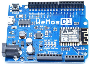
All sensors were tested with code individually on Arduino IDE, to make sure they worked. That was all good. Then came putting the code together and getting digital pins to play nice together. The ESP8266 has a lot fewer digital I/O than Atmel 328P boards like UNO, etc. It has only one analog input. The pinouts can be confusing with multiple versions of RX/TX and SPI printed on the boards themselves. To get everything to work together, I assumed only one of each. I2C comes to the rescue by sharing communication port. Just have to make sure the addresses of your sensors do not overlap. Using the Adafruit sketch for scanning attached I2C devices clears that question fast. next I wanted to test the WiFi capability of NodeMCU from my shed. I don’t know if it was the fact it got power from USB port or that particular unit had antenna issues, but it had spotty connectivity and would lose signal often. I decided to get a WeMos board, which still uses ESP8266, but has an UNO footprint and standard power connector. I figured with larger capacitors, and fact I could feed it 9V, it might have steady power to deliver the data over WiFi. Long story short….the WeMos has connected and delivered data consistently.
As with the NodeMCU, you have to name your pins by what they are (like D5, D7, and A0) due to pin mapping. Everything works as it should when that is done. Due to the lower number of GPIO on ESP8266, uploading and running firmware can be a little more difficult. One example is I could not sync during upload with IRQ using D4 or D8. I ended up using D7 and that was fine. All kinds of reset occurrences can happen with ESP8266. Most cases, it can be one line of code referring to a library. I learned that I would only make one change to code at a time and between each change, upload firmware and test with serial monitor. In the end, I narrowed down most resets and continuous reboots to use of interrupts. In the final code for this weather station, there are 3 sensors that use interrupts: Lightning board, anemometer, and rain bucket. What was happening ended up coming from sending data to server over WiFi and interrupts would blow it up.
The key to getting everything running smoothly was to turn off the interrupts right before connecting and sending data to the emoncms server. After the send, you perform attachinterrupts again for the IRQs. Here is how the sequence would go in the code – the data transfer to webserver happens between the detach and re-attach interrupts as shown here:
  detachInterrupt(digitalPinToInterrupt(IRQ_pin));
  //added these
  detachInterrupt(digitalPinToInterrupt(intAnem));
  detachInterrupt(digitalPinToInterrupt(intRain));
Serial.print("Requesting URL: "); Serial.println(url); // This will send the request to the server client.print(String("GET ") + url + " HTTP/1.1\r\n" + "Host: " + host + "\r\n" + "Connection: close\r\n\r\n"); unsigned long timeout = millis(); while (client.available() == 0) { if (millis() - timeout > 5000) { Serial.println(">>> Client Timeout !"); Serial.println("Disconnecting..."); client.stop(); return; } } // Read all the lines of the reply from server and print them to Serial while (client.available()) { String line = client.readStringUntil('\r'); Serial.print(line); } Serial.println(); Serial.println("normal closing connection"); client.stop(); attachInterrupt(digitalPinToInterrupt(IRQ_pin), alert, RISING); //added these attachInterrupt(intAnem, serviceInterruptAnem, RISING); attachInterrupt(intRain, serviceInterruptRain, RISING);
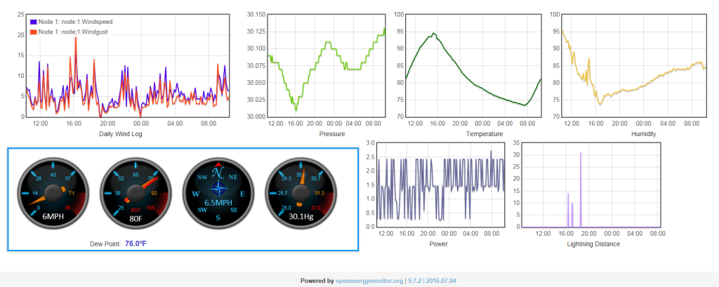
I decided to use the OpenEnergyMonitor platform for recording and logging my weather. This is a great way to display your sensors. The widgets are already created and the graphs and display can be customized to your satisfaction. The platform runs on a server of your choice (I chose my Beagleboard-XM running Ubuntu 12.04) and is PHP-based and uses MySQL as storage for data. Here is an example of the emonCMS custom web view: