
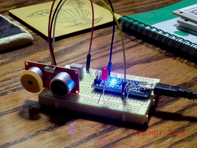
Finally had some time to tinker again. This time working on the distance sensing function of eventual autonomic robot. I turned to a good ol’ Arduino for the physical IO. I got a Nano, and this is a sweet little microprocessor. All the functions of an Uno crammed into a little DIP from factor. For testing things out it is stellar. Just plug into USB port of PC and run your IDE of choice and your off. I decided on a Seeed Studio ultrasonic rangefinder. This is pretty much the same as a Parrallax Ping sensor, or the SRF-05 rangefinders. This Seed studio unit has 1cm resolution and pretty inexpensive.
My goal is to get the forward focal point more resolution (like a telescopic lens vs. a fisheye). Ultimately I could and should use a laser rangefinder, but this approach is quick & dirty and ripe for tinkering. My thinking was that perhaps I could narrow the dispersion of the ultrasound at least on the transmitting side. I knew that because the sensors are separated by about an inch, narrowing the input or receiving side would reduce the amount of echo reception perhaps too much and give haphazard results. Ultrasonic waves travel in a more focused pattern compared to audible waves in the first place. So by creating a smaller source of waves, I believe the “beam” will be narrower. My thought was to cover up the exposed area of the transmitting speaker – they are little speakers in there (like whizzer cones in old automobile full-range speakers).
Upon testing, I found that the stream of data (microsecond time) was pretty consistent with stray numbers that were off the chart determined to be the reflected ultrasound inside the chamber getting out through the hole. By filtering that out in the Arduino sketch, I could get reasonable results.

Since the above output was centimeters, I think the resolution is decent enough. Before the lens mask and filtering, I had all kinds of values in a pretty wide range. My guess it was from the transducer dispersal pattern catching an object behind or to the side of what I thought was in front of the rangefinder. I will modify the code to test output in a graph to test the narrowness of the beam on real world objects. I will either grab the values and put in Excel or write some code using Processing (www.processing.org) to show the graph realtime.
Speaking of Processing – I love that software suite, platform, IDE or what ever you want to call it. It uses the same format and syntax as Arduino sketches right down to the graphic interface. So if you know “C like” sketches, using Processing will come to you quickly. I found this awesome sketch by Lucky Larry in the UK who wrote a sketch for his pan-tilt rig using a rangefinder. He wrote a graphical radar-like realtime screen output from the rangefinder and it is pretty slick. I modified it a bit for my purposes, but kudos to him for the original sketch.
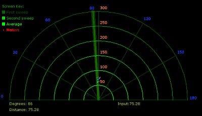
So that is the screen you see while Processing is running the sketch. Basically, you run your rangefinder sketch on the Arduino – make sure the serial output screen is not open. Then you run the Processing sketch which reads the serial stream. I modified the code to show “ping” reflections as dots instead of polygon areas. I also changed it sweep only 4 degrees on either side of 90 degrees. I can see a lot of potential with Processing and the Arduino family of processor boards for physical computing feedback.