
More on the NodeMCU (V1)….. This little booger is great! I have tried all kinds of wireless upload solutions with Arduino (Olimexino with ESP8266, Nano with various wireless devices) and the end result of actually uploading the sketch never succeeded. It all had to do with the reset aspect which causes the bootloader to accept code and overwrite existing code. I tried all kinds of elaborate methods: softserial, trigger words that closed reset pin, and a few others I can’t remember now. I just wanted a way to be able to update firmware/sketches while the device was far away and locked up without having to hookup to a usb cable to do updating.
Enter the NodeMCU version of the ESP8266. Out of the box it works with the Arduino IDE. No need to mess with LUA. Once I got the latest ESP8266 code from Github to replace what was in the IDE, everything worked like a charm. On my Windows 7 PC, that library went into appdata\local\arduino15\packages\ESP8266. The version that really worked was 2.3, as the version 2.2 that came with IDE didn’t really work with wireless upload. The key is the ArduinoOTA library that was fixed and updated. The key for me getting it to work was with the reset. In the default code, the reset is called when the OTA function failed. To get it to really work, you do the reset after the upload and Bingo! it all works.
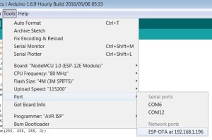
After your first USB sketch upload with the OTA library and code in place, you have to close down Arduino IDE, and then restart IDE for the OTA port to show up. Not doing this step at first made me think the library was not working. The image above shows the OTA port under ‘network ports’. This capability all comes from Arduino Yun wifi procedures, so anyone with that board would be familiar with the network port in the list.
There really isn’t much more to it than that. The only downside as far as I can tell is the serial monitor falls out of the mix. You cannot use network port with serial monitor because it relies on Yun firmware that asks for SSH password. You can still use the USB port powering the nodeMCU board if you use another terminal program (like Putty) to see what is coming over serial.
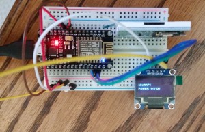
My solution was to hookup an OLED screen to the board and display anything I needed to monitor. The beauty of using an I2C OLED panel is it only uses 2 wires. I have a TFT LCD panel which is SPI, and still may use this in the end as it has SD card storage as a bonus. But for testing, the OLED is easy and just works.
Here is the sketch code that grabs a static IP address and allows over-the-air uploading. It also has the OLED bits for variable monitoring and feedback.
#include <ESP8266WiFi.h>
#include <ESP8266mDNS.h>
#include <WiFiUdp.h>
#include <ArduinoOTA.h>
#include <Wire.h>
#include “SSD1306.h” // alias for `#include “SSD1306Wire.h”`
SSD1306 display(0x3c, D2, D1);const char* ssid = “your_local_ssid”;
const char* password = “your_wifi_password”;
const char* host = “ESP-OTA”;#define led_pin BUILTIN_LED
#define blu_pin D4
#define beat 450
IPAddress ip(192, 168, 1, 196); //Node static IP
IPAddress gateway(192, 168, 1, 1);
IPAddress subnet(255, 255, 255, 0);
void setup() {
Serial.begin(57600);// Initialising the UI will init the display too.
display.init();display.flipScreenVertically();
display.setFont(ArialMT_Plain_10);
delay(25);pinMode(led_pin, OUTPUT);
Serial.println(“”);
Serial.println(“Booting”);
WiFi.mode(WIFI_STA);WiFi.begin(ssid, password);
WiFi.config(ip, gateway, subnet);
while (WiFi.waitForConnectResult() != WL_CONNECTED) {
WiFi.begin(ssid, password);
Serial.println(“Retrying connection…”);
delay(5);
}
ArduinoOTA.setHostname(host);
ArduinoOTA.onStart([]() { // switch off all the PWMs during upgrade
analogWrite(led_pin, 0);
});ArduinoOTA.onEnd([]() { // do a fancy thing with our board led at end
for (int i = 0; i < 80; i++)
{
digitalWrite(led_pin, HIGH);
delay(i * 2);
digitalWrite(led_pin, LOW);
delay(i * 2);
}
ESP.restart();
});ArduinoOTA.onError([](ota_error_t error) {
ESP.restart();
});/* setup the OTA server */
ArduinoOTA.begin();
Serial.println(“Ready”);
Serial.print(“IP address: “);
Serial.println(WiFi.localIP());
Serial.println(“Now Online!”);
}void loop() {
// clear the display
display.clear();
float power = WiFi.RSSI();
String strpower = String(power, 1);
display.setTextAlignment(TEXT_ALIGN_LEFT);
display.setFont(ArialMT_Plain_10);
display.drawString(0, 18, ssid);
display.setFont(ArialMT_Plain_10);
display.drawString(0, 32, “POWER: ” + strpower);
display.display();
analogWrite(blu_pin, power);
ArduinoOTA.handle();
heartbeat();
delay(30);
}void heartbeat() {
digitalWrite(led_pin, HIGH);
delay(beat);
digitalWrite(led_pin, LOW);
delay(beat);
}